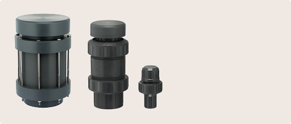
Compact, Self-Closing Vacuum Breakers
Series VB/VBM/VBS
Compact, Self-Closing Vacuum Breakers Protect Tanks and Piping Systems Against Hazards, Damage and Financial Losses Caused by Vacuum
Features/Benefits with Proper Installation:
- Designed to protect enclosed tanks from collapse or structural damage during draining.
- Eliminates siphoning of dangerous fluids.
- Prevents vacuum which can cause damage to sensitive instruments and filters.
- Normally-closed design prevents fugitive emissions from leaving system.
- Ensures against replacement of damaged expensive equipment and avoids critical system downtime.
- Patented diaphragm design assures dependable, repetitive, bubble-tight sealing in VBM and VB; PFA encapsulated spring and special poppet provide identical performance in VBS design.
- For corrosive or ultra-pure liquid applications.
- Sizes: ½", ¾", 1", 1½", 2", 3" and 4".
- Materials: PVC, CPVC, Polypro, PVDF, PTFE.
Series VBM ½", ¾" & 1" Construction & Materials
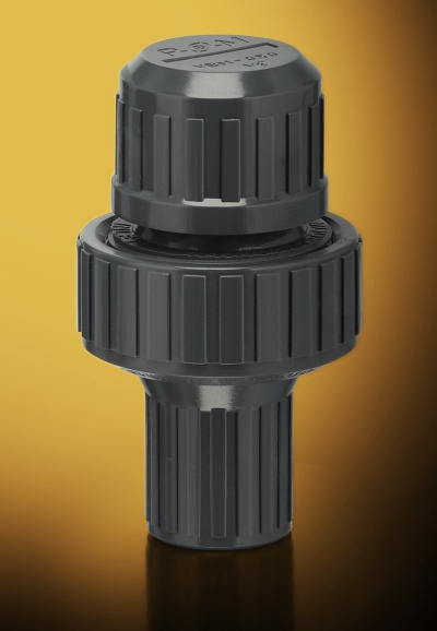
Series VBM Vacuum Breakers are molded of Geon® type 1, grade 1, PVC(Polyvinyl Chloride), Corzan® CPVC, Glass-filled Polypropylene and Kynar® PVDF in pipe connection sizes ½", ¾" and 1".
A machined version, Series VB is available in PTFE in sizes ¾" and 1".
Diaphragms are of EPDM or FKM (Viton). Fasteners are not used on Series VBM. Fasteners used on PTFE Series VB are stainless steel and are NOT in contact with process liquid.
For alternate materials, please consult factory. Minimum quantities apply.
Threaded connections are standard on all models. Socket ends, BSP threads, JIS and DIN connections are available on all sizes and materials except PTFE VB. Inlet connection is shipped with standard dust cap. Cap is removable for applications where pipe connection is desired due to location, potential hazard, etc. The inlet connection is identical to the connection on the system side of the valve. If your application requires an unusual connection, custom material or configuration, please contact our Technical Team at 973-256-3000.
Series VBS 1½" & 2" Construction & Materials
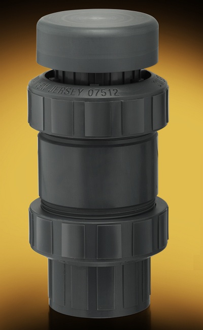
VBS Vacuum Breakers are available in Geon® PVC, Natural Polypropylene, Corzan® CPVC and Kynar® PVDF in sizes 1½" and 2". Standard dust caps match body material with the exception of PVDF models which are natural polypropylene; PVDF dust cap is optional. No fasteners are used on Series VBS in 1½" & 2" sizes. The self-guided spring is completely encapsulated (not coated) with PFA. The encapsulation is not "adehered" to the spring. It flexes independently of the spring and does not crack or flake the way coatings can. This encapsulation has been tested for over 1,000,000 cycles in laboratory conditions with no ill effects.
Series VBS seals are EPDM or FKM.
For alternate materials, please consult factory. Minimum quantities apply.
Threaded connections are standard on all models. Socket ends, BSP threads, JIS and DIN connections are available on all sizes and materials. Inlet connection is shipped with standard dust cap. Cap is removable for applications where pipe connection is desired due to location, potential hazard, etc. The inlet connection is identical to the connection on the system side of the valve. In these two sizes the VBS connections are removable and the valve is easy to clean and service. If your application requires an unusual connection, custom material or configuration, please contact our Technical Team at 973-256-3000.
Series VBS 3" & 4" Construction & Materials
VBS Vacuum Breakers are available in Geon® PVC, Natural Polypropylene, Corzan® CPVC and Kynar® PVDF in sizes 3" and 4". Standard dust caps match body material with the exception of PVDF models which are natural polypropylene; PVDF dust cap is optional. External, non-wetted fasteners are used on Series VBS in 3" & 4" sizes and are 300 series stainless steel. The self-guided spring is completely encapsulated (not coated) with PFA. The encapsulation is not "adehered" to the spring. It flexes independently of the spring and does not crack or flake the way coatings can. This encapsulation has been tested for over 1,000,000 cycles in laboratory conditions with no ill effects.
Series VBS seals are EPDM or FKM.
For alternate materials, please consult factory. Minimum quantities apply.
Threaded connections are standard on all models. Socket ends, BSP threads, JIS and DIN connections are available on all sizes and materials. Inlet connection is shipped with standard dust cap. Cap is removable for applications where pipe connection is desired due to location, potential hazard, etc. The inlet connection is identical to the connection on the system side of the valve. If your application requires an unusual connection, custom material or configuration, please contact our Technical Team at 973-256-3000.
Connection Types:
Threaded connections are standard on all models. U.S. socket end connectors are available on all sizes and materials except PTFE VB. BSP, JIS, and metric DIN connections also available on VBM & VBS. Inlet connection is shipped with standard dust cap. Cap is removable for applications where pipe connection is desired due to location, potential hazard, etc. The inlet connection is identical to the connection on the system side of the valve. If your application requires an unusual connection, custom material or configuration, please contact our Technical Team at 973-256-3000.
Design:
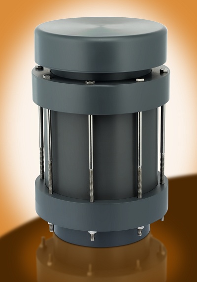
The Plast-O-Matic Series VB and VBM Vacuum Breakers have only one moving part - the patented self-sealing diaphragm, and this provides both design simplicity and maximum operating dependability. This normally-closed design seals in the identical location every time producing a very dependable, long-life seal.
Series VBS Vacuum Breakers feature a corrosion resistant PFA encapsulated spring which acts on a poppet seal that neither sticks nor chatters. Maximum working pressure is 100 PSI @ 75°F (6,9 bar @ 24°C). Operation and Installation:Plast-O-Matic Vacuum Breakers feature a patented, normally-closed, design that can be mounted in any position; however, upright is recommended. For enclosed tank applications, mounting should be at the highest point of the tank.
Uses of Vacuum Breakers in a Typical Piping System
In the diagram above, a vacuum breaker is positioned on top of the supply tank to prevent implosion when the tank is drained. A second vacuum breaker is shown on a tee to prevent siphon in a vertical drop. This creates a pocket of air in the riser, lateral line, and drop to "break" the suction that would otherwise be created in the drop when the pump is turned off. The blue color indicates liquid in the system when the pump is turned off. When the system is re-started, an air release valve positioned along the high point of the pipeline is necessary to expel the air pocket for safe and efficient operation. Additional air release valves may be necessary at other points, depending upon the size and complexity of the pipeline. Placement of degassing valves (not shown) varies from system to system.
Performance:
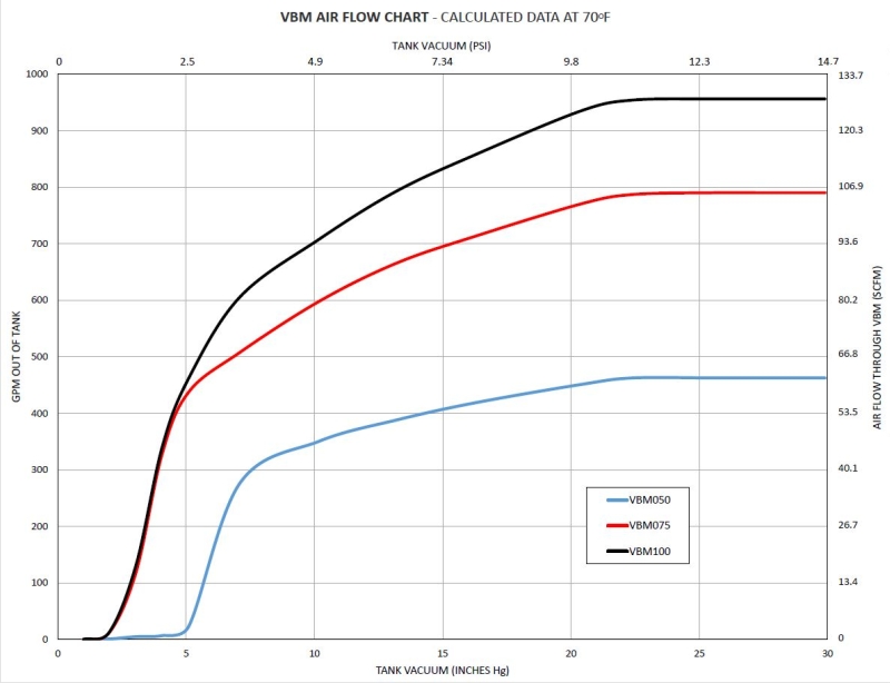
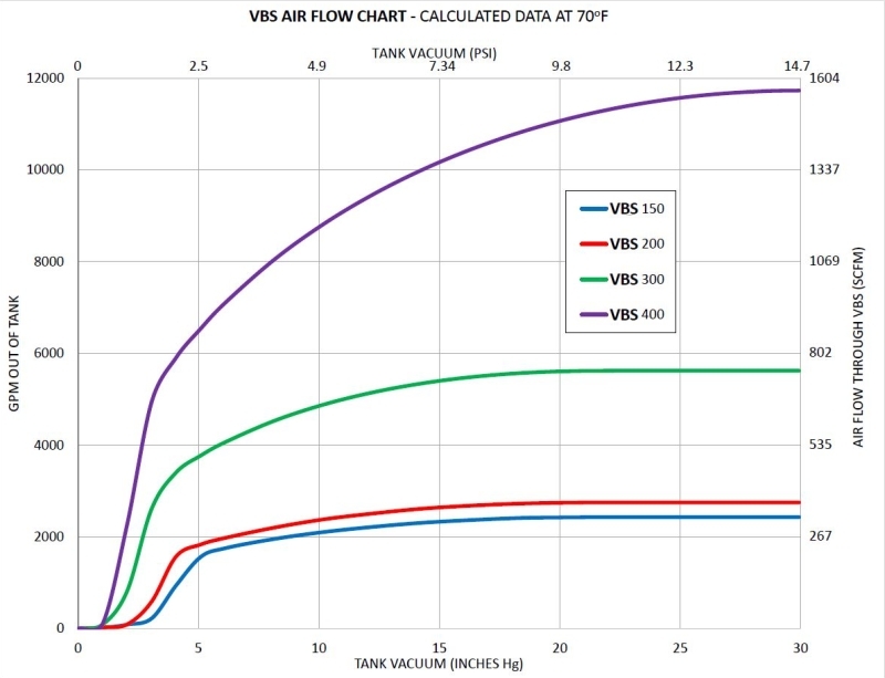
These Vacuum Breakers will begin to break a vacuum at approximately 2 inches of mercury (1.0 PSI or 0,07 Bar negative pressure). Therefore the user must assure that the tank can withstand much more vacuum. This information must be obtained from the manufacturer of the tank. It is strongly advised to use a minimum 3X safety factor. The chart below shows air flow (SCFM) through the valve, vs. vacuum (inches of Hg) at the outlet of the valve, with atmospheric pressure at the inlet of the valve. These are calculated values, thus the need to apply a safety factor is important. The user of the valve must assure that the air flow through the valve will be enough to compensate for tank vacuum. Tank vacuum is a function of tank size, and rate at which liquid is flowing out of the tank.
 Explanation of Graph:
- The above graphs relate liquid flow leaving an enclosed tank to the resulting vacuum created in the tank as air is entering the tank through the Vacuum Breakers.
- To use the graph, determine the rate of flow when draining the tank in SCFM and from that location on the vertical axis read across to the graph of the proper vacuum breaker size. At this intersection of the graph read down to the horizontal axis and determine the vacuum for the tank. This is the recommended vacuum rating of the tank which must be checked with the tank manufacturer's rating to be sure the tank is strong enough.
Anti-Siphon Applications:
For these applications the Vacuum Breakers must be installed in a "U-bend" at least 30 inches (2½ feet or 76 cm) above the highest liquid level. Depending on the safety factor desired for Anti-Siphoning this height would become 60 inches (5 feet or 152 cm) at 2 times safety factor which is recommended by Plast-O-Matic.
Use Caution in Dangerous Applications:
In the event a diaphragm failure could cause spraying of a dangerous liquid onto nearby equipment or personnel, or simply into the atmosphere where breathing the vapors would be dangerous, it is strongly advised to use a Plast-O-Matic Check Valve in lieu of the Vacuum Breaker, and pipe the vent or inlet side of the check valve to a safe remote location. The Check Valve will have the same flow capabilities of the Vacuum Breaker, and contains the same design.
Elimination of Vacuum in a System:
To prevent instrument or system malfunction, the same considerations are involved as in the tank application. The vacuum breaker should be installed at the highest location in the system. Plast-O-Matic Vacuum Breakers can be mounted in any position since they are self-sealing and do not rely on gravity to operate; however, upright is preferred. Also see Anti-Siphon section.
Dimensions: 
Series VBM - Molded Models: PVC, GPP, CPVC, PVDF
PIPE
SIZE |
A |
B |
C |
D |
| In. |
mm |
In. |
mm |
In. |
mm |
In. |
mm |
| ½" |
4.3 |
110 |
1.3 |
33 |
2.4 |
62 |
1.9 |
48 |
| ¾" |
4.7 |
120 |
1.6 |
39 |
2.8 |
72 |
2.5 |
64 |
| 1" |
5.1 |
130 |
1.9 |
48 |
2.8 |
72 |
2.5 |
64 |
Series VB - Machined Models: PTFE| ¾" | 4.5 | 114 | 1.9 | 48 | 3.0 | 76 | 2.0 | 51 |
|---|
| 1" | 4.5 | 114 | 1.9 | 48 | 3.0 | 76 | 2.0 | 51 |
|---|
Series VBS - PVC, PP, CPVC, PVDF
| 1-½" |
7.9 |
193 |
2.5 |
64 |
4.1 |
104 |
3.5 |
89 |
| 2" |
8.5 |
209 |
3.0 |
76 |
4.1 |
104 |
3.5 |
89 |
| 3" |
10.5 |
268 |
4.2 |
107 |
5.8 |
147 |
5.5 |
140 |
| 4" |
12.83 |
326 |
5.75 |
146 |
7.88 |
200 |
7.5 |
191 |
Ordering Information:
| Ordering Information for Series VB & VBM |
| Pipe Size |
Series VBM-PVC
Viton Seals |
Series VBM-CPVC
Viton Seals |
Series VBM-GPP
Viton Seals |
Series VB-TF
Viton Seals |
|---|
| ½" |
VBM050V-PV |
VBM050V-CP |
VBM050V-PP |
n.a. |
| ¾" |
VBM075V-PV |
VBM075V-CP |
VBM075V-PP |
VB075V-TF |
| 1" |
VBM100V-PV |
VBM100V-CP |
VBM100V-PP |
VB100V-TF |
| For PVDF, change suffix to "PF". Choice of socket or threaded connection for all types & sizes except PTFE version series "VB". |
| Ordering Information for Series VBS |
|---|
| Pipe Size |
PVC
Viton Seals |
Natural Polypro
Viton Seals |
Kynar PVDF
Viton Seals |
Corzan CPVC
Viton Seals |
| 1-½" |
VBS150V-PV |
VBS150V-PP |
VBS150V-PF |
VBS150V-CP |
| 2" |
VBS200V-PV |
VBS200V-PP |
VBS200V-PF |
VBS200V-CP |
| 3" |
VBS300V-PV |
VBS300V-PP |
VBS300V-PF |
VBS300V-CP |
| 4" |
VBS400V-PV |
VBS400V-PP |
VBS400V-PF |
VBS400V-CP |
| Choice of socket or threaded connection for all types & sizes of Series VBS. |

Pressure/Temperature Ratings:
Series VBM - Molded Models: PVC, CPVC, GPP & PVDF
Valve
Body
Material |
Valve
Diaphragm
Material |
Maximum Working Pressure (PSI) |
|---|
| 75ºF |
110ºF |
140ºF |
180ºF |
220ºF |
240ºF |
284ºF |
|---|
| (24ºC) |
(43ºC) |
(60ºC) |
(82ºC) |
(104ºC) |
(115ºC) |
(140ºC) |
| PVC |
EPDM
Viton |
100
100 |
100
100 |
40
40 |
NR
NR |
NR
NR |
NR
NR |
NR
NR |
|---|
| CPVC |
EPDM
Viton |
100
100 |
100
100 |
80
80 |
40
40 |
NR
NR |
NR
NR |
NR
NR |
|---|
| GPP |
EPDM
Viton |
100
100 |
100
100 |
100
100 |
80
80 |
NR
NR |
NR
NR | NR
NR |
|---|
| PVDF |
EPDM
Viton |
100
100 |
100
100 |
100
100 |
100
100 |
NR
60 |
NR
30 |
NR
10 |
Series VB - Machined PTFE Models
Valve
Body
Material |
Valve
Diaphragm
Material |
Maximum Working Pressure (PSI) |
| 75ºF |
110ºF |
140ºF |
180ºF |
220ºF |
240ºF |
284ºF |
| (24ºC) |
(43ºC) |
(60ºC) |
(82ºC) |
(104ºC) |
(115ºC) |
(140ºC) |
| PTFE |
EPDM
Viton |
100
100 |
90
90 |
80
80 |
70
70 |
NR
40 |
NR
20 |
NR
10 |
Series VBS - PVC, CPVC, GPP & PVDFValve
Body
Material | Valve
Diaphragm
Material | Maximum Working Pressure (PSI) |
|---|
| 75ºF |
110ºF |
140ºF |
180ºF |
220ºF |
240ºF |
284ºF |
|---|
| (24ºC) |
(43ºC) |
(60ºC) |
(82ºC) |
(104ºC) |
(115ºC) |
(140ºC) |
| PVC |
EPDM
Viton |
100
100 |
100
100 |
40
40 |
NR
NR |
NR
NR |
NR
NR |
NR
NR |
| CPVC |
EPDM
Viton |
100
100 |
100
100 |
80
80 |
40
40 |
NR
NR |
NR
NR |
NR
NR |
|---|
| PP |
EPDM
Viton |
100
100 |
100
100 |
100
100 |
80
80 |
NR
NR |
NR
NR |
NR
NR |
| PVDF |
EPDM
Viton |
100
100 |
100
100 |
100
100 |
100
100 |
NR
60 |
NR
30 |
NR
10 |
|---|
For complete pressure & temperature ratings (including CPVC) please click here for .pdf version of data sheet.
CAD Files
1/2" VBM .dwg
1 1/2" VBS .dwg
3" VBS .dwg

HELPFUL LINKS:"Anti Siphon Valve" Series RVDT
If the problem you are trying to solve or prevent is siphon from a tank due to negative pressure downstream of the pump, this may be the type of valve you actually need. If you are unsure, please call our Technical group at 973-256-3000 for free assistance.
Series CK/CKD/CKM/CKS Check Valves
This is the general check valve page, and it may be the page you linked to this one from. As you may know, vacuum breakers are a check valve that is fitted with a special protective cap. Without the cap, the check valve is subject to all sorts of environmental hazards, so we recommend a true vacuum breaker be used for vacuum breaker applications. But -- as stated above -- in some cases you may want to break the tank vacuum by drawing air (or other) from an alternate location. In these and other cases, it is more appropriate to use a check valve with the appropriate piping. Please use the check valve link, or contact our Technical Group at (973) 256-3000 for assistance.
Vacuum Breaker Applications
Examples of how vacuum breakers are used to prevent damage in tanks and piping systems.
Cleanroom preparation and bagging, "CDB Procedure"
Description of the optional Class 100 cleanroom cleaning, inspection, capping and bagging.
5 Most Common Mistakes When Specifying Valves
This is a very helpful, brief tutorial written by Andy Ryan, Plast-O-Matic's Director of Sales.
Valve Pressure Loss & Flow - Q&A and Equations
(Explains Cv and Delta P, how to better specify valves, etc.)
For a .PDF file - please click below:
Vacuum Breakers - (PDF)
|